Flaring Systems and Pressure Relief: A Comprehensive Guide to Plant Safety and Overpressure Management
Importance of Flaring Systems: Why Do We Need Them?
If industrial systems are designed to operate flawlessly, why do process engineers include relief and flaring systems? The answer lies in safeguarding against overpressure scenarios. No system is immune to human error or equipment failure, and these systems are essential to ensure safety and prevent catastrophic failures.
The Role of HAZOP in System Design
Addressing these potential risks is a critical part of the HAZOP (Hazard and Operability) study. This reminds me of these long & extensive HAZOP sessions that involve a multidisciplinary team working collaboratively to analyze every possible failure scenario.
Who attends a HAZOP?
- Process Designers – responsible for the system layout and operations.
- Facilitators – guide the team through the HAZOP process.
- Instrumentation & Control Experts – ensure proper functioning of safety devices.
- Operations Team Members – provide practical insights from daily plant operations.
- Third-Party Safety Specialists (in some cases) – bring external expertise to enhance plant safety.
How HAZOP Works
During a HAZOP meeting, the team meticulously examines Process & Instrumentation Diagrams (P&IDs) and Process Flow Diagrams (PFDs). Every line, valve, and instrument are analyzed to identify potential issues and develop appropriate safeguards. By anticipating these issues, the team ensures that relief systems, like flares, are in place to handle emergencies, ultimately protecting both the plant and personnel.
Process Design: A Human Body Analogy
Renowned process engineer Norman Lieberman once compared process design to the human body. Like the body, when something goes wrong, the system responds. Plant operations reflect the combined experience of the engineers who designed them and the operators who run them. And just as a skilled doctor can diagnose a health issue, a knowledgeable process engineer can spot design flaws.
One of the most common mistakes made by inexperienced designers is over- or under-sizing equipment. This can lead to inefficiencies or even safety risks. Designing a flaring system might seem unnecessary when a process runs smoothly under normal conditions, but what happens when things go wrong?
Why Flaring Systems Are Essential
Imagine a scenario where:
- The inlet valve of a process system accidentally opens, but the outlet is blocked. Pressure will build rapidly, jeopardizing the integrity of the equipment.
- Or consider a distillation column where the cooling system fails. Without adequate cooling, the lighter components won't condense, causing the column's pressure to rise dangerously.
In these cases, the flaring system vents excess pressure and protecting critical equipment. Without it, the system could rupture, leading to significant damage, downtime, and potential hazards to personnel.
Typical events that require pressure relief:
· Accidental closure of outlet valve or opening of inlet valve
· Return valve failure
· Runaway reactions
· Mal-operation or abnormal operation.
· Equipment/ service failure or utility failure
· Operator failures
· Equipment failures
Flaring vs. Other Safety Measures
When faced with a potential release event, process designers have four main options:
1️) Dispose of the material.
2️) Contain it within a safe boundary.
3️) Treat the release to neutralize or reduce its hazards.
4️) Flare it, safely burning off the excess gas.
The decision on which method to use depends on several key factors:
- Physical State: Is the stream a gas, liquid, or a mixture?
- Toxicity & Flammability: How dangerous is the released material to people and the environment?
- Separation Feasibility: Can liquids and gases be easily separated for safer handling?
- Dilution Potential: Is it possible to dilute the release below the Lower Explosive Limit (LEL) or a non-toxic concentration?
Flaring is a controlled process where waste gases, primarily hydrocarbons, are directed to a designated elevated or ground-level flare stack and burned in an open flame. This safety mechanism serves two critical purposes:
1️) Preventing the direct release of harmful gases into the atmosphere, which can pose environmental and safety risks.
2️) Safely disposing of excess hydrocarbons that cannot be processed or reused, converting them into less harmful byproducts like carbon dioxide and water vapor.
By burning these gases instead of venting them, flaring minimizes the risk of explosion, reduces the environmental impact, and ensures a more controlled and safe disposal process.
Industry Standards:
Most common industry standard for flare system include standards from American Petroleum industry, which are the following:
1- API 520 -Sizing, Selection & installation of pressure relief systems.
2- API STD 521- Pressure Relieving and Depressurizing systems.
3- API STD 526 flanged steel pressure relief systems.
4- API 537 Flare details for general refinery and petrochemical refinery.
5- API 2000- venting of atmospheric and low-pressure storage tanks.
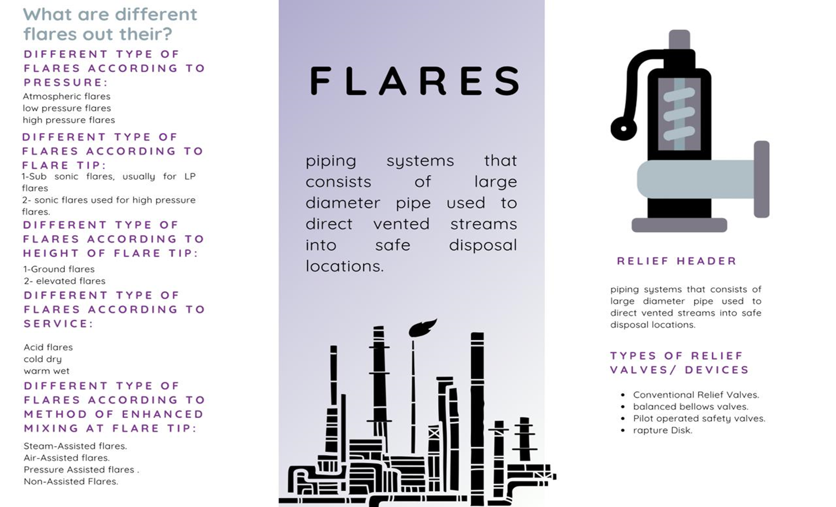
Flare types
Flares are categorized either by the height of the flare tip (Ground or Elevated) or method of enhancing mixing at flare tips like steam assisted or air assisted flares. Other characterizations are also mentioned sometimes regarding exit velocity & Service (Acid flares, Cold dry or Warm wet). Common flare types will be mentioned in this article but not all.
Segregation of flares according to pressure:
1- Atmospheric.
2- Low Pressure.
3- High Pressure.
Steam Assisted flares:
These flares are elevated systems positioned above ground level, featuring single burner tips. This type is commonly used in refineries and chemical plants. To ensure proper mixing, steam is injected into the combustion zone to create turbulence and draw air into the flame, promoting complete combustion.
Air Assisted flares:
Air-assisted flares use forced air to supply combustion air for smokeless flames. The burners have a spider-shaped design, and the airflow can be regulated by a fan or blower connected to the grid. A key advantage is that this type of flare can be used when steam is unavailable. However, for large gas volumes, air-assisted flares are less economical compared to steam-assisted flares.
Pressure Assisted flares:
These flares use the vent pressure to facilitate mixing at the burner tip, usually have multiple burner heads.
Non-Assisted flares (non-smokeless flames):
Non-assisted flares do not use auxiliary steam or air to improve mixing of air into the flame. They are typically used for gases that are smokeless, such as hydrogen or hydrogen sulfide, or when smoke is not a concern in a particular case.
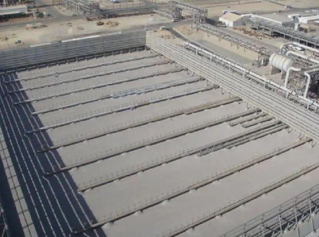
Multipoint Ground Flares:
The main advantage of multipoint ground flares is low radiation. Instead of using a single burner, multiple small-diameter burners are employed, improving mixing by distributing the flaring process across several smaller units rather than one single burner.
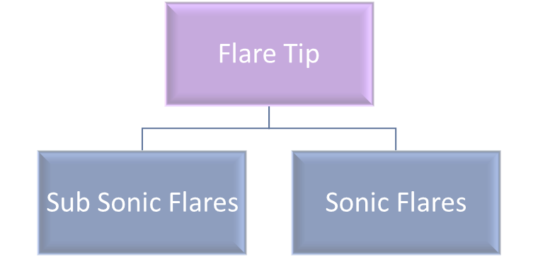
Sonic flares:
In sonic flares, gas exits the flare tip at speeds of at least Mach 1. This high velocity induces air into the flame, improving mixing and combustion efficiency. The result is a whiter flame and a relatively low Ringelmann number (explained in a later section). Sonic flares are used for high-pressure systems.
Subsonic Flares
Subsonic flares are designed for low-pressure (LP) systems. Usually sonic and subsonic flares are used by process designers to denote high pressure and low-pressure flares.
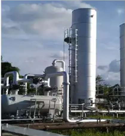
Elevated flares:
These flares require less ground space and are more cost effective.
Enclosed flares:
Also known as vapor combustors, this type of flare is used when visible flame is not acceptable. They can reduce noise and radiation.
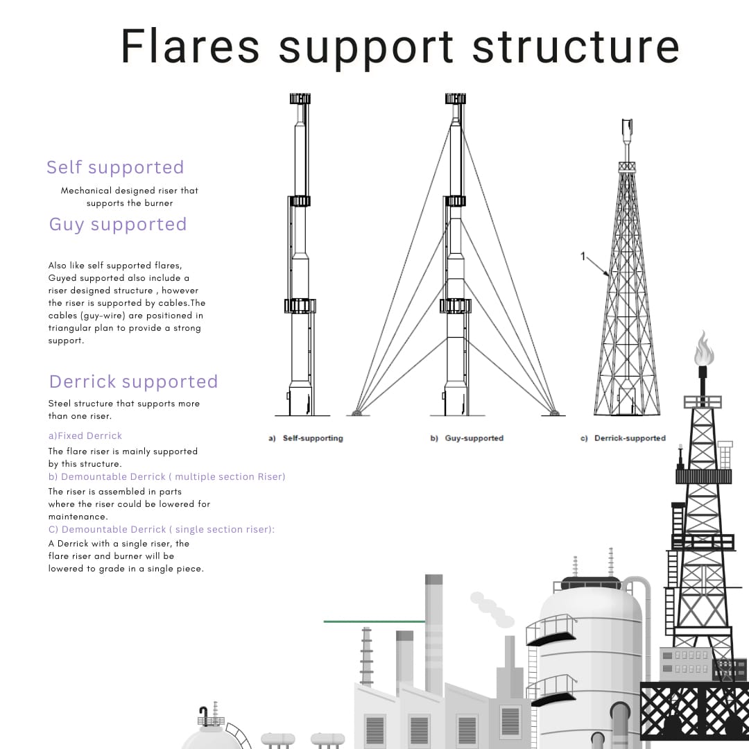
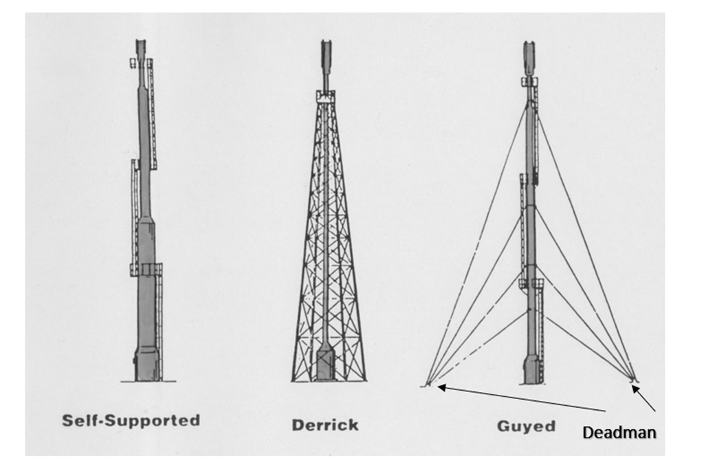
Flare structure
· Self-supported flare stack: Mechanical
· Guy wired supported flare stack.
· Derrik supported flare stack.
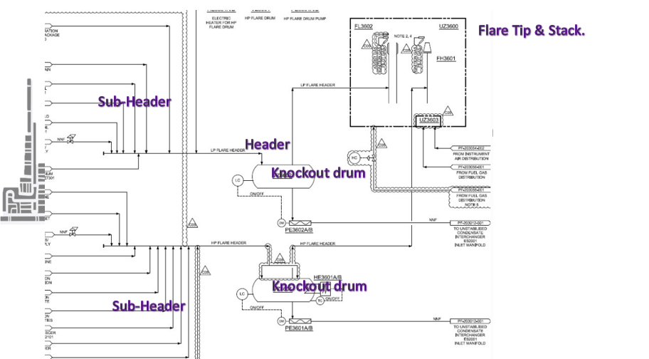
What are flare headers?
properly sized piping system that will deliver and collect relief gases to flare, when sizing relief headers the vapor flow compressibility must be considered to limit what is known as “Choking”.
Pilot/Pilot igniter:
A pilot igniter is used to ignite relieved gas. This stream is always on whether there is relief gas going to flare or not. The following table illustrates the total number of pilots required in correlation to flare Burner diameter. A very important point to consider is for a single pilot flare, if the pilot fails the ignition system will fail as well. To add redundancy to the plant, it is more logical to install at least two pilots even for a small burner system.
|
Minimum Number of Pilots |
Flare Burner Diameter (mm) |
Flare Burner diameter (in) |
|
1 |
Up to 200 |
Up to 8 |
|
2 |
Up to 600 |
Up to 24 |
|
3 |
Up to 1050 |
Up to 42 |
|
4 |
Up to 1500 |
Up to 60 |
Atmospheric venting, when this option is allowed
Atmospheric venting is often considered a highly reliable disposal method due to its simplicity and effectiveness. When applicable, it offers a significant advantage. Note that this only allowed in certain conditions.
Here's how it works:
1️) For flammable gases, if the exit velocity from the vent stack is sufficient to entrain enough air, that the gas will be diluted below its Lower Explosive Limit (LEL), significantly reducing the risk of ignition. In such cases, atmospheric venting is permitted.
2️) For toxic gases, atmospheric venting is allowed only if the released gas can disperse to a concentration below toxic thresholds, ensuring the safety of personnel and the environment.
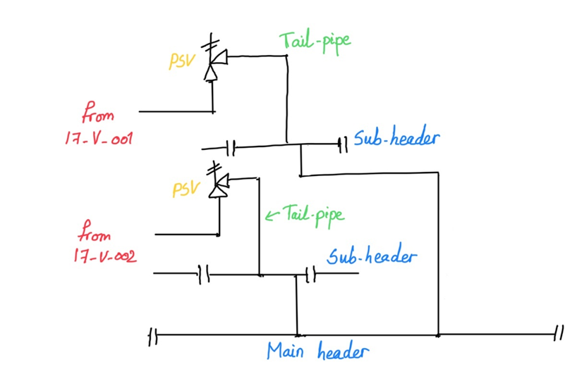
Venting to relief header
Toxic or flammable gases which are not suited for atmospheric discharge are vented into a relief header connected to a scrubbing system or flare systems.
Relief header is a piping system consisting of large pipes that directs fluid to flare in case of relief event. Connected to the flare headers are tailpipes coming from different process equipment (As illustrated in Figure 4).
All these pipes must have enough diameter to reduce backpressure when several relief devices are opened at the same time. Relief header and tail pipe are demonstrated on Figure 4.
Types of relief devices
Conventional relief valve:
1. spring-loaded relief valves are adjusted to a certain force or compression of the spring, when the pressure of the system reaches the set pressure, thus when the force applied to the plunger exceeded the force provided by the spring the valve lifts.
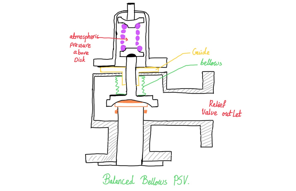
2.Balanced bellows or balanced relief valve is a type of conventional relief valve that has an additional component called bellows; the conventional spring-loaded valve has a certain limitation which is the maximum back pressure. The balanced bellows valve on the other hand, reaches higher percentages of backpressure compared to a conventional relief valve. This type of valve is recommended usually to avoid the influence of backpressure. The purpose of the bellows is to isolate the area above the disk from superimposed backpressure.
3.Pilot operated safety valve can go to 90% backpressure of set pressure, this valve uses a pilot operated valve to open and close the valve. The valve containing a sensing line that will sense the pressure at the Pressure relief valve (PRV) inlet. The sensing line will also provide fluid to keep the valve closed. When the equipment reaches the set pressure the pilot valve will open.
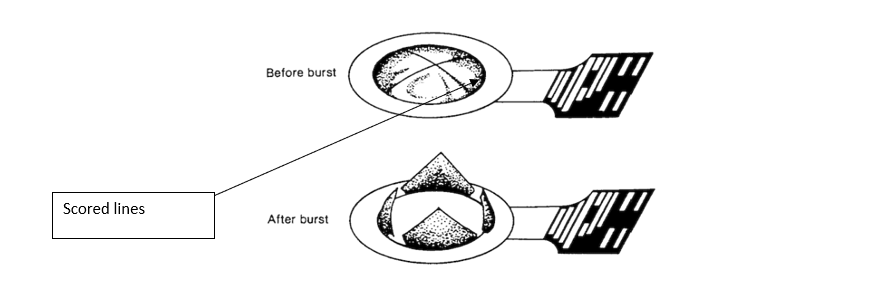
4.Rapture disk is a non-reclosing relief device containing a metal or graphite membrane that will burst at a specific pressure used for overpressure or vacuum protection. The rapture desk has scores (scored lines) with predefine area of weakness. In corrosive service the rapture disk will be installed upstream a relief valve to protect the valve seat from corrosion.
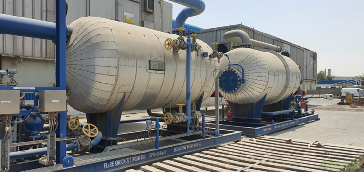
Emergency gas/Liquid Separation:
A knockout drum is a critical safety device used in pressure relief systems. It separates gas from liquid before directing the gas to the flare system. The fluid entering the knockout drum can be:
- Vapor
- Liquid
- Two-phase (vapor-liquid mixture)
The liquid phase may originate from the process itself or form during gas expansion due to the Joule-Thomson effect.
Why Are Knockout Drums Important?
- Protecting the Flare Stack from Liquid Carryover
- Risk: If liquid enter the flare stack, they can spread around the stack area.
- Consequence: The burning liquid can cause fires around the flare, posing a significant safety hazard.
- Ensuring Complete Combustion
- Risk: Even small amounts of liquid in the flare system may not burn completely.
- Consequence: This incomplete combustion leads to the formation of harmful gases like carbon monoxide (CO) and other pollutants, affecting air quality and environmental safety.
Purge Gas
During normal operation the amount of gas going to the flare header is very small, the purge gas supply is consistent to ensure that a certain exit velocity is maintained from the flare tip and to maintain a sweep of liquid inside the relief header to the knockout drum, and to avoid any air ingress from atmosphere to the flare stack.
Flare seal drum
Flare seal drum provides extra protection to protect the flaring system from air ingress through the tip (additional to the purge gas). If in any case the atmospheric air enters the header, this is very dangerous as it may cause an explosion inside the header affecting the integrity of the line. Thus, Air ingression from atmosphere back to the header must be always avoided. The idea of the seal drum is that if there is any air pressure it will be slowed down by the liquid seal (Mostly water) before it able to access the main flare header. This provides extra protection besides the purge gas.
Other devices are used to prevent air pressure, these include both molecular seals, and velocity seals.
Flare tips/Smokeless operation:
One of my professors once shared a personal story with us. He had the opportunity to work abroad, so he relocated with his family and settled near a chemical plant. Living close to the plant was convenient, as it allowed him to commute to work easily. During a lecture on process refining, he leaned on the desk in front of him, looked up thoughtfully, and began to recount his experience.
"After some time, my son started showing symptoms of asthma," he said. "I took him to the hospital, and the doctor confirmed the diagnosis. My son was prescribed asthma medication for years."
He went on to explain that as long as they lived near the plant, his son had to rely on the medication. However, when he moved to a new job in a different location, the family left the area.
"Once we moved," he continued, "all of his symptoms disappeared. Today, he’s grown and completely healthy. It was then that I realized with certainty because he had developed asthma—it was due to the pollution from that chemical plant"
This story always comes to mind when I see thick black smoke billowing from a flare stack. But why did his son develop asthma? To understand this, we need to look at a concept called smoke opacity.
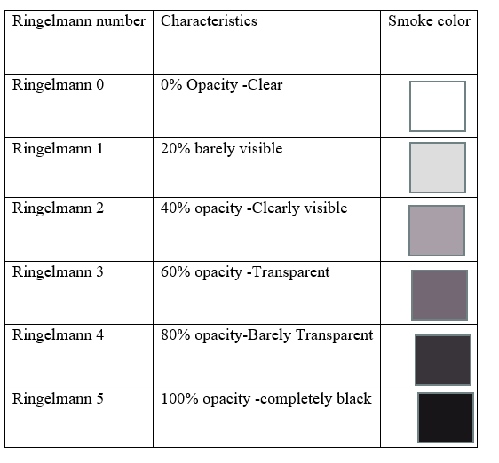
Smoke opacity is measured using the Ringelmann Scale, which ranges from 0 to 5. A Ringelmann number of 0 represents clear air, while a 5 indicates thick, opaque black smoke. The chart below illustrates the Ringelmann scale.
If your flare tip is producing black smoke with a Ringelmann number of 5, it’s a clear sign that something is wrong. Here are a few things to check:
- Ensure that your air blower is functioning properly.
- Verify the steam or air flow, especially if you have a steam- or air-assisted flare system.
- Optimize the air-to-fuel ratio to promote complete combustion of the fuel.
The issue with black smoke isn't just aesthetic—it's dangerous. Incomplete combustion produces carbon monoxide (CO), a harmful gas. Additionally, black smoke contains soot, which can accumulate and block flare nozzles, compromising the flare system’s efficiency.
Even more concerning is the fact that black smoke contains fine particulate matter (PM), which can pose serious health risks, including asthma, respiratory diseases, and even cancer.
Proper maintenance and monitoring of flare systems are essential to prevent these issues and ensure both environmental and human safety.

Flame Front Generator (FEG):
The system operates by introducing a gas/air mixture into a small line leading to a pilot burner. Once the line is filled with the gas/air mixture, a spark ignites it, and the resulting flame travels swiftly along the line to the pilot, igniting the pilot burner.
During startup, fuel gas is supplied from a system at ground level. Once the line is fully purged and filled with the gas/air mix, the mixture is ignited, creating a "fireball" that travels to the flare pilot, ensuring safe and reliable ignition. The Flame Front Generator (FFG) system can be operated either manually or automatically, providing flexibility and safety in operation. The Flame Front Generator (FEG) panel, illustrated in the below figure.
Glossary
Operating pressure: Maximum Pressure in which the vessel could operate at. Usually, the operating pressure is defined by designers for your plant.
Maximum Operating Pressure is usually 5% above the operating pressure, in case there is an upset in the process plant a 5% margin is given for operator above operating pressure which is the maximum pressure in which the vessel could be operated at.
Design pressure: Most severe condition the vessel could be exposed to during normal operation. Design pressure as a rule of thumb is 10% margin from maximum operating pressure.
MAWP: Design pressure based on constructed vessel. This value is provided by the manufacturer. MAWP is equal or higher than Design Pressure.
Set Pressure is the point in which the relief device is set to open. Set pressure is usually assigned at design pressure.
Overpressure is pressure above the set pressure that the relief device could operate at.
Back pressure is the pressure at the relief valve outlet.
Superimposed backpressure is the PRV backpressure when the valve is closed at the valve outlet.