Isolation philosophy
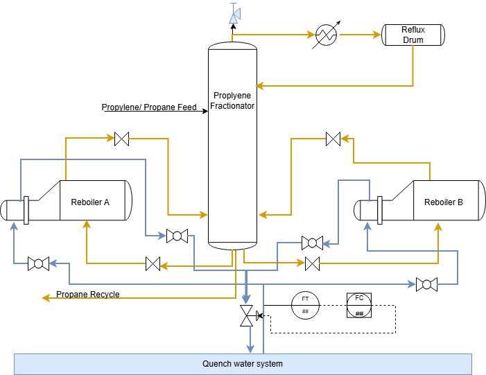
On the morning of June 13, 2013, operators at the Williams Olefins Plant in Geismar, Louisiana, were dealing with what appeared to be a routine operational problem.
At a propylene fractionation unit that separates a mixture of propane and propylene. The fractionator relied on two reboilers to supply the heat required for the stripping section of the column. The reboilers were shell-and-tube heat exchangers. Hydrocarbon flowed through the shell side, while hot water circulated through the tube side. Over time, the hot water carried small amounts of oily tar that accumulated inside the tubes, resulting in fouling and reduced heat transfer. To restore performance, the tube bundles required periodic cleaning.
In the original design, cleaning a reboiler required shutting down the fractionator. To improve plant availability, a modification was implemented in 2001 that allowed one reboiler to remain in service while the other was isolated and placed on standby.
On the day of the incident, Nothing about the system appeared unusual. In fact, the problem operators observed was one they had seen before. plant personnel observed that the water flow rate through the operating reboiler had declined. The most likely cause was tube fouling, and the decision was made to switch service to the standby reboiler.
What was not known at the time was that the standby reboiler was not empty.
While the exchanger was isolated, propane-rich hydrocarbon had slowly leaked past a closed block valve and accumulated inside the equipment in the last 16 months. The valve was assumed to provide isolation, but like all valves, it was not leak-tight forever. Over time, a significant inventory of flammable liquid had collected inside the standby exchanger.
When hot water was introduced into the tube side, heat was transferred to the trapped propane. The liquid rapidly vaporized, causing the pressure inside the exchanger to rise. Under normal circumstances, such pressure would be relieved through a pressure relief valve. However, in the standby configuration, the reboiler had been isolated from its pressure relief path and was no longer protected by the PSV, as the block valve to the fractionator was kept closed.
The exchanger now contained a source of pressure but had no effective means of relieving it.
As vaporization continued, the pressure increased beyond the mechanical limits of the exchanger. The resulting rupture released a large quantity of hydrocarbon, which ignited shortly afterward. The explosion killed two workers and injured more than one hundred others.
The main contributor to this incident is that the exchanger was isolated from PSV , however taking a second glance to the operation also highlights a fundamental weakness in the isolation philosophy. The standby exchanger was isolated by a single block valve. The design implicitly assumed that the valve would provide perfect long-term isolation. In reality, valves leak. The question is not whether a valve can leak, but what happens when it does.
The Williams incident demonstrates two important lessons. First, equipment should never be isolated from its pressure relief device if a credible source of pressure remains. Second, the level of isolation must be appropriate for the hazard being controlled.
To understand why this distinction is so important, we must first understand the concept of isolation philosophy
Isolation philosophy:
The type of isolation involved in the Williams incident was a valved isolation of the non-proved type.
Isolation methods are generally classified into three categories:
- Category I – Positive Isolation
- Category II – Proved Isolation
- Category III – Non-Proved Isolation
Understanding the differences between these categories is essential for ensuring personnel safety and preventing the unintended release of hazardous materials.
Non-Proved Valved Isolation
Non-proved isolation relies solely on the closure of valves and provides no means of confirming that the isolation is actually effective. Common examples include:
- Single Block (SB)
- Double Block (DB)
Single Block (SB)
A Single Block arrangement uses one valve to separate the equipment from the live process. While this configuration may appear adequate, it depends entirely on the valve maintaining a tight seal.
If the valve leaks internally, process fluid can enter the equipment that is believed to be isolated. Since there is no method of verifying valve integrity, the leak may go unnoticed until personnel are exposed to the hazard.
Double Block (DB)
A Double Block arrangement uses two valves installed in series. The second valve acts as a backup barrier should the first valve fail.
At first glance, this appears safer than a Single Block arrangement. However, important questions remain:
- How can we determine if the first valve is leaking?
- What if both valves leak?
- Can we confidently rely on this arrangement for vessel entry or other high-risk work?
The challenge is that a Double Block arrangement still provides no way of verifying the effectiveness of the isolation. Both valves may appear closed, yet leakage could still be occurring. For this reason, Single Block and Double Block arrangements are classified as non-proved isolations.
Proved Valved Isolation
To overcome the limitations of non-proved isolation, the industry uses proved isolation arrangements. These configurations include a means of confirming whether leakage is occurring across the isolation barrier.
The most common examples are:
- Single Block and Bleed (SBB)
- Double Block and Bleed (DBB)
Single Block and Bleed (SBB)
In a Single Block and Bleed arrangement, a bleed valve is installed downstream of the block valve on the side being isolated.
If the block valve leaks, process fluid will be released through the bleed valve, immediately indicating that the isolation has failed. The bleed point therefore provides evidence that the barrier is either holding or leaking.
Double Block and Bleed (DBB)
A Double Block and Bleed arrangement consists of two block valves with a bleed valve located between them.
If the upstream valve leaks, the leakage can be detected through the bleed point before it reaches the equipment being worked on. The second block valve provides an additional layer of protection, while the bleed point provides verification of the isolation integrity.
This combination of redundancy and verification makes DBB one of the most commonly used isolation methods for maintenance activities and certain confined space entries involving hazardous fluids.
Positive Isolation – The Highest Level of Protection
Although proved isolation significantly improves safety, there are situations where reliance on valves alone is not considered sufficient.
In these cases, a positive isolation is required.
Unlike valved isolations, positive isolation provides a physical separation between the live process and the equipment being worked on. Because it does not depend on valve integrity, it offers the highest level of protection.
Positive isolation can be achieved by:
- Removing a spool piece and installing blinds or blank flanges on both open ends.
- Turning a spectacle blind to the blind position.
- Installing a spade (slip blind) between flanges.
- Replacing a spacer with a line blind.
These methods create a visible and verifiable barrier that prevents process fluids from reaching the isolated equipment.
Choosing the Right Isolation
The selection of an isolation method should always be based on the level of risk involved. Non-proved isolations may be acceptable for low-risk activities, while proved isolations provide a higher degree of confidence by allowing verification of valve integrity.
For high-risk work, particularly vessel entry involving hydrocarbons, toxic substances, or other hazardous fluids, positive isolation is often required because it eliminates dependence on valve performance and provides the greatest level of protection for personnel.
The Williams incident serves as a reminder that isolation is not simply about closing valves it is about ensuring that hazardous energy and materials are positively controlled before people are exposed to the risk.
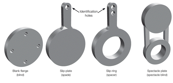
Figure 2: isolation spades and spectacle plates.